26 December 2023

Luce di cortesia per il baule dell'auto

Arriva l'auto nuova. E' dotata di sensori di parcheggio, retrocamera, frenata assistita, sensori di collisione, sensore di pioggia, sensore luci, cruise control, navigatore, sedili riscaldati, specchietti motorizzati, il profumo di auto nuova. Ha anche le ruote, i sedili ed un volante, certo. Fai un bel giro. Poi ti capita di fare la spesa e scegli il supermercato con ampio parcheggio coperto dove puoi lasciarla lontana dagli sportelli altrui.

Arrivi con le borse, apri il bagagliaio e.... buio. Nero! Sbirci dentro per cercare l'interruttore della luce di cortesia ma non c'è. Non c'è nemmeno la luce! Hai speso tante migliaia di euro per accaparrarti il frutto del lavoro di tanti progettisti e LORO si dimenticano di mettere un piccolo, economico ma utilissimo sistema di illuminazione nel bagagliaio! Tra l'altro, parere personale, apprezzeresti molto di più la luce nel bagagliaio degli specchietti retrovisori regolabili elettricamente. E costa pure meno. O sbaglio?

Ma oggi la soluzione c'è. Si tratta di installare una "luce LED notturna con sensore di movimento" che viene normalmente proposta per l'illuminazione negli armadi. E' alimentata a batteria ricaricabile entrocontenuta ed è leggerissima. Io l'ho fissata sotto la cappelliera, dapprima con i magneti in dotazione, e poi affiancati da velcro incollato con supercolla ("At...ck" o "Bos..k"): un lato sulla luce, l'altro sulla superficie interna della cappelliera.

E signori, questa soluzione non fa solo da luce di cortesia per il baule. Dato che si può spostare, può seguirci nel cofano motore se dobbiamo controllare i liquidi o accompagnare la lettura di un libro/giornale senza scaricare la batteria dell'auto (che se poi non parte son dolori).

La batteria dura almeno un paio di mesi e si può ricaricare mentre si è in viaggio usando un cavetto USB adatto (la mia barra LED è arrivata con il suo cavetto).

Spesa totale? 5 euro più dieci minuti del proprio tempo.

Nota sull'utilizzo di questa versione. La barra luminosa si controlla con un singolo pulsante: alla prima pressione resta sempre accesa, con un'altra pressione (fa un lampeggio) si accende quando rileva movimento ed è buio, con un'altra pressione (fa tre lampeggi) si accende quanto rileva movimento indipendentemente dalla luminosità esterna. Con la quarta pressione si spegne. Tenendo premuto il pulsantino si attiva il dimmer per regolare la luminosità. Quindi per l'utilizzo nel bagagliaio, partendo da spenta, premete due o tre volte il pulsantino.

Per i curiosi, l'auto in questione è una Suzuki Ignis del 2017. La stessa auto prodotta nel 2020 ha la luce di cortesia nel bagagliaio, ma questa soluzione fa più luce!

23 December 2023

Battery of Braun 5514 shaver

I have a cordless hair&beard "styling kit" from Braun, model 5514, that doesn't hold the charge anymore. I use my soldering iron more often than this shaver so I have no idea how long the stand-by period is. Still, loosing the charge in one week is not acceptable.

There is a good video on YT showing how to open it. You need a thin and a thicker plastic card/tool to pop open the top cover and a small straight screwdriver. 

There are two batteries wired in series, in my case they are marked as "SUPPO HS-AAA0.75" NIMH 1.2V. The guy in the video shows the same model.

Now, if you search for that string you can buy a replacement at 1/3rd of the price for a new tool. But those batteries are just AAA NiMH rechargeable cells with solder tabs, with a capacity of at least 750 mAh (so if you buy them of 1000 mAh that's fine, it will take longer to reach full charge).

Then it's a matter of cutting off old batteries and soldering in new ones.

Someone might mumble that it should not be so hard to replace a battery. This tool is designed to be used in wet environments so it is waterproof. This means that it's already gold it is not sealed. Also the motor in the shaver creates vibrations and it's better to have batteries (and everything else) held together as strong as possible.

09 December 2023

High-Voltage High-Z DIY probe

As a self-assignment for troubleshooting the Hameg oscilloscope, I needed to measure kiloVolts. The world agrees that you need to arrange a resistive voltage divider using an high impedance (10 Mohm) voltmeter. 

For example if your voltmeter has an input impedance of 10 Mohm you need a 90 Mohm resistor in series to obtain a 1:10 ratio:

 (kV)------/\/\/\/\/------[Voltmeter]------(GND)

            90 Mohm         10 Mohm

I looked for suitable resistors at home and I found 4x 10 Mohm and 5x 5.27 Mohm, all 10% or more. So theoretically I could reach 66 Mohm which gives about 1:7,6 ratio. The chosen voltmeter can measure 500V, that's up to 3800V "input".

Since it is hard to accurately measure high resistances and their value may change with voltage I decided to determine the ratio with an experiment.

Given that the input impedance of an instrument might be unknown or different from the spec sheet, I empirically found the ratio of different voltmeters I own. First measure a DC voltage V1 using the voltmeter alone. Then measure again the same source adding the big resistor in series, you get V2. V1/V2 is the ratio of that resistor using that voltmeter at that voltage range.

A high voltage probe with very high impedance is built and inserted into the plastic tubes of felt-tip markers.
A high-Z probe for HV.

I repeated the experiment at higher voltages, like 80V and 300V, to observe that the ratio increases 1-2% with applied voltage (300V vs 10V). I settled to 1:8.02 for my setup.

I completed the build with a label on the probe that reminds its usage and characteristics.

IMPORTANT. Whenever you work on live circuits that use high voltages prepare the measurement setup when everything is off and unplugged from the grid. Then put one hand in the pocket, reconnect power and press "ON". Before doing any adjustment switch off the device under test and unplug the AC cord. If you are unsure, let someone expert do it.

Why didn't I aim for the 1:10 ratio? First and foremost because I needed "now" to measure that voltage. Second because I wanted to use those high value resistors. Third because it's hard (and expensive) to get a perfect 1:10 ratio, so I would have used a calculator anyway: any ratio is good, then! Fourth because I had an excuse to use one of the vintage calculators from my collection.


05 December 2023

Troubleshooting an Hameg HM203-6 oscilloscope - no trace

Right after fixing the high voltage being too high (-2500V vs -1900V) on the Hameg HM203-6 oscilloscope, the trace disappeared. Note that I was able to see the trace at the restored -1900V cathode voltage and I was after the ineffective un/blanking control.

HV was there. Un/blanking signal was there. What could have possibly gone bad, now?

When operating in XY mode (or component tester mode if your scope has it), there is no retrace or blanking: you should always get at least a dot somewhere on the screen (be careful with phosphor burning!). I was not getting a beam, even in XY mode. So something was blocking the electron beam into the CRT: either missing acceleration or blocking grid at wrong voltage. That is where I concentrated my efforts.

I knew that BF199 was bad. Even with a new one nothing happened. BF440 was good as well as the optocoupler. At least they tested as expected on the DVM at low voltage.

Don't forget that components may (will) show a different behavior or value depending on the voltage applied. That's why I changed three 68 pF 2 kV capacitors that have been pinpointed as being prone to failure in online forums.

When all voltages were measured as expected I moved on to in-circuit component testing. The device MUST be powered off and unplugged! I take no responsibility for whatever damage to animated or inanimate beings you may cause.

Remove socketed components as they can be tested individually. Then proceed with this methodology:

  • resistors should exhibit the stamped value or lower, because they are in parallel with other resistors and alike: replace if value is too high or too low;
  • diodes should conduct in the A>K sense and exhibit an open-circuit or high impedance on reverse polarization: replace if forward and reverse voltages are too low for the diode type, or if it's open

I did not need to test capacitors as I found two open resistors and one shorted diode. I mark them in red in the schematic diagram excerpt below. See the thread on eevblog for the whole story.

A part of Hameg 203-6 oscilloscope circuit diagram.

So the Hameg HM203-6 symptoms were:

  1. trace too bright and not going dim/off with intensity control plus
  2. not un/blanking 

They were caused by:

  1. broken high voltage regulation, which probably lead to
  2. un/blanking failure and
  3. blocking grid control failure 

Components replaced:

  • one 741 op-amp IC
  • 3 high voltage 68 pF capacitors (perhaps not needed)
  • one BF199 transistor
  • two resistors
  • one diode 

Cost about 5€(2023)  and 10 man/hours. Troubleshooting value: invaluable.

30 November 2023

Troubleshooting an Hameg HM203-6 oscilloscope - high voltage on CRT

I used the Hameg HM203-6 scope to test the Tennis-for-Two emulator I quickly built in November 2023. I also carried it to the exhibition venue as a backup. When it returned home I felt the urge to play with this analog oscilloscope that was lucky enough to be extracted from my pile of "probably to-be-fixed stuff".

So, what was wrong with it?

  1. compressed traces, about 0.7x shorter on both axes, and too bright;
  2. unblanking not working properly (it's the circuit that blanks the CRT electron beam when it returns to the left);
  3. rusty contacts.


Too high HV symptoms on a Hameg HM203-6 oscilloscope. For better viewing traces have been right-aligned. This way the unblanking problem is also visible.
Too high HV symptoms on a Hameg HM203-6 oscilloscope.
 

Hameg's were built when SMD was not a thing yet (mine is from 1988) and they use common (...back then...) parts. Therefore tracing the fault doesn't require a microscope and a replacement component can be found.

For the compressed bright traces I posted a request on eevblog and few fellas responded with very useful tips. Actually they noticed the problem with unblanking! The verdict is: High-Voltage is too high. It makes sense: higher voltage means faster electron beam that both gets less time for full deflection and hits harder the phosphor. I had checked the 150V line for deflection circuitry, which was fine. Sure enough the -1900V was at -2550V.

[Measuring kiloVolts is an interesting journey in itself and there will be a dedicated post.]

On eevblog was suggested that IC502, a 741 op-amp, might be faulty: "check that the voltage between inputs is few milliVolts max." I measured 455 mV, replaced the IC, -1900V was restored and traces "uncompressed". Considering the cost of a 741 I will not look any further for faults in the HV regulator, leaving a deeper inspection in case the problem arises again.

There is still the issue with unblanking. Something might have been damaged running at -2500V. There are three suspects: 68pF 2kV capacitors, the optocoupler, a couple of transistors. The latter two components are socket, most likely because they were prone to failure.

As for rusty contacts, they probably need some exercise, the most annoying being the "INV" button on both channels.

29 November 2023

Tennis for Two emulator

The secret project that went live on November 17th, 2023, was an emulator of the Tennis-for-Two game from 1958. It has been built for MuPIn - Museo Piemontese dell'Informatica - that held an exhibition of tennis (retro)videogames for the ATP Finals 2023.

Several videogames were on display and could be played, like the original Pong from 1972 up to a Wii.

There was a panel describing what should be the first videogame in history, the Tennis-for-Two developed to let visitors (taxpayers) of a USA laboratory interact with their technology. When I saw it I searched online for a modern emulator, found a 2008 project and I knew I could build it with parts I had at home. 

So who visited the exhibition in the second weekend could play an emulator or Tennis-for-Two on a Tektronix oscilloscope.

Fun fact: people spent most of their visit-play time at Tennis-for-Two and Pong games.

The video above shows one of my tests on my Hameg analog oscilloscope, shot with the smartphone that didn't want to focus on the CRT trace. Please refer to the link above for the circuit diagram and firmware (ATmega168 and up).


19 November 2023

PCB design: unfortunate position for a microcontroller IC

The last PCB I designed includes an ATtiny85 microcontroller. Since it will not need many updates I did not include the ICSP header for reprogramming. The first time I needed to swap out the '85 I realised I forgot to leave some room for pulling the IC from the socket. HAH!


I usually insert a small flat screwdriver under the IC and gently lift it up. In the configuration above it is impossible to get in from the left and just slightly easier from the right paying attention to the resistors.

Lesson learned.


17 November 2023

Teaser 2 - secret project

Second part - of three - of the secret project going live in 4 hours in Torino...


Teaser - secret project

This board is from a secret project that will go live tonight at an exhibition. I realised I could build it last Sunday and I knew I already had everything at home, like a good lot of 4k7 resistors :)


This quick project obviously got highest priority and everything else went into stand-by, like the optical TX/RX and 24 GHz.

Looks like November is the month of self-imposed challenges for me.


01 November 2023

OptoSupply OS5RKA5102P and OS5RKA5111P THT ultrabright LEDs

Lately I am playing with LEDs, trying to build a pair of optical transceivers. The TX side will use some very bright 5 mm red LEDs made by OptoSupply. I chose those with 8° and 15° beamwidth. They are OS5RKA5102P and OS5RKA5111P respectively and they should emit 100'000 mcd each, which is quite impressive, also on your retina if you look straight into them.

For the records, one TX will have 8° LEDs, the second will use 15°.

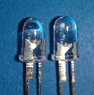
Besides their weird leg shape that requires a custom footprint (I've done it for KiCad) the problem with these LEDs is that they look very similar and you can easily mix them. So, here is a closeup that helps distinguish which is which.

Close-up picture of narrow beamwidth OptoSupply LEDs.
Left is the 8° OS5RKA5102P, right is the 15° OS5RKA5111P.

Left is the 8° OS5RKA5102P, right is the 15° OS5RKA5111P. Physically the 8° has a narrower body, larger anode area and smaller tab on the anode leg.


LEDs and the bags they came in, to confirm part No.!

While testing the 4x4 array I noticed that one LED was dimmer: a closer inspection confirmed that I had soldered a 15° LED amongst 8°. If they worked with the same current that wouldn't be a bit problem, but it is not the case with these two models.

30 October 2023

KiCad TO-92L footprint for hand soldering

Today I received a small batch of PCBs - THT for hand soldering - and halfway building I had to troubleshoot a short on the input Vcc line.

I had a suspect: the 78L05. Well, not "him", but how I soldered it. While I had plenty of space on the board, I used the TO-92L footprint where pins are very close to each other. If you add a bit of rush, sub-optimal lighting and worsening eyesight (with age), a bridge is almost granted.

KiCad footprint for TO-92L components.
One of the TO-92 footprints available in KiCad.

Next time I will use a wider footprint, nevermind if I have to bend pins. No wonder KiCad has TO-92L_Inline_Wide!


23 October 2023

Polarization of LD1115H vs CDM324

Before popping the HLK LD1115H radars I noticed that I could get a stronger signal when the orientation of the antenna arrays between TX and RX (CDM-324) was 90 degrees apart.

I found that the signal was stronger when the modules were positioned - relative to each other - as shown in the picture below.

This relative position provided strongest signal in the lab environment.

Before conducting any "long" distance test it is worth checking the effect of "swapping" polarization on one side.


21 October 2023

S 042 P and UAA170 from the cellar

At a local flea market I bought a plastic drawer parts storage cabinet with 25 compartments. Drawers had unsorted components inside, mainly carbon resistors with 1W or more rating. At home I emptied everything so that I could wash it and I found some interesting parts, like:

  • "S 042 P" mixer IC
  • "UAA170" LED driver
  • "TDA1200" FM-IF
  • SGS BFT 56 with extra long legs

Considering the ICs I found in the lot I think the previous owner wanted to build a stereo FM receiver kit from the Italian magazine "Nuova Elettronica" (https://www.adrirobot.it/lx-193-sintonizzatore-fm-con-decoder-stereo/).

When I was a teen I was fascinated by the project of a shortwave receiver using an "S 042 P" IC, that I've never been able to meet in the wild for the following 35 years! I think it was already discontinued or obsolete when the article was printed. I wonder if I could finally build that project now!

In the meantime I might try building a running light with the UAA170 and a 555. It could even be made into a freeform sculpture .


17 October 2023

Overvoltage on HLK LD-1115H - don't

In case you wonder how these radar modules handle overvoltage, the answer is: very bad. I gave 12V to both of my specimen while trying to understand where the 5 MHz modulation was coming from (TX or RX CDM-324 side) and they let out the magic smoke.

I removed both 3V regulators but the 3V line is still shorted to ground. There is a little chance that something else blew before the small 24 GHz chip but I doubt so.

I will check with Mauro if it is worth continuing with these modules since the output power is much lower than CDM-324 or the original Infineon part. We do need the tamed frequency drift these radars offer, but RF power is useful too to get decent "DX" results.

24 GHz QRX.

30 September 2023

Let's modulate the HLK-LD1115H (WBFM)

Since the aim of all the activities on the HLK-LD1115H radar module is to come up with a simple 24 GHz transceiver, it was time to have it send some information. Unless you opt for an on-off modulation like Morse code, the easiest way is to fiddle with the VCO control voltage to obtain frequency modulation. An easy "entry point" is shown in the picture. That node is in the middle of a resistive voltage divide and it's also quite easy to solder to (I do hand soldering!).

Detail picture of accessible VCO control pads to change the frequency of the radar module.
Accessible VCO control pads.

How much voltage is needed? Looking at the chip specs, the VCO moves 650 MHz per Volt. Since we need to be able to receive the FM with available tools, the resulting RF signal should have a maximum bandwidth of 250 kHz. Also, considering the phase noise observed on the non-modulated signal (remember: we don't know if the source is in the TX or RX side, or both), the wider the modulation, the better.

A rough calculation tells us:

250 [kHz] / 650000 [kHz/V] = 385 [microV]

That's not a big deal: just divide whatever voltage you have with large enough resistors and start from "all the way down". I used a signal generator set at about 800 Hz in high-Z output, fully attenuated and fed to the radar through a 10x oscilloscope probe and a 100 nF capacitor.

With the same receiving setup as the previous experiment/post I achieved easy modulation of this 24 GHz radar module. I also compared the SDR signal with a real wideband FM radio and the latter gave much better audio signal to my ears (less noise).

Next step will be to pull radar frequencies close together and into the HAM allocation (24.000 to 24.050 GHz, they are a bit high on 24.100 GHz now) and use one radar as receiving end without bypassing the onboard "low frequency" amplifier (the op-amp has a 10 MHz GBW).


26 September 2023

Emission of HLK-LD1115H as seen with a CDM324

In the picture below we can witness two radar modules looking at each other.

A CDM324 basic radar module was connected to an RTL-SDR to check the emission of a HLK-LD1115H. The greatest fear was that the HLK carried too much noise requiring an extremely wide modulation, but the picture shows a situation that is not worse than 2x CDM324 talking to each other. And we should consider that with this setup it is impossible to tell which radar is noisier.

The short-term frequency instability is probably caused by CDM-324 sensitivity to temperature variations, as it was fully exposed to ambient air.

The transmitting radar shows about -15 MHz drift at warm up in the first couple of minutes. I could also confirm that the transmission is continuous and not modulated.

On the second HLK module I own I pulled to ground the TXON control pin. Curiously on the serial port output it would report detection of movement and presence, alas with a lower intensity than the stock counterpart. With the receiving setup I could confirm that disabling TX introduces about 40 dB attenuation in the RF output.

I like the fact that the HLK-LD1115H can detect a movement 40 dB down, as it gives some headroom for completing a QSO at "some" distance. My current "record" with 2x CDM324 is 70 meters, without parabolic dish(es). 


What's next? Either trying to inject a modulation or pull the frequency closer to the other HLK and repeat the receiving experiment.

24 September 2023

Prescaler output to VO pin (HLK-LD1115H)

Now that the prescaler has been enabled in the Hi-Sense HLK-LD1115H 24 GHz radar module, I would like to have that signal easily accessible.

Let's dive into another hardware mod.

As already observed, the DIVOUT signal goes to pin 12 of the microprocessor. Additionally there is a 100 ohm resistor in series, close to the uP. The firmware on the microprocessor seems to ignore this new input, so the 100 ohm resistor is a good point to intercept the prescaler output.

Next to it there's another 100 ohm resistor (a tiny black rectangle), that protects the VO movement/presence detection signal coming out of pin 11 of the microprocessor (tnx Mauro for the info!). Cool, VO goes all the way to the pin header!

Here is the plan: remove both 100 ohm resistors and create a jumper as shown in the picture below. If you are brave enough you can use a 100 ohm resistor, like rotating 90 degrees one of the originals. Click on the picture to get a larger version and see the small details.

(Not reversible) Mod to bring DIVOUT to VO pin.


Guess what? It works. Now it's easier to see frequency drift with temperature and experiment with thermal insulation.

Next step will be to disable the transmission in one module so that it becomes "receive only" (act on TXON signal) and try to receive the other module. This might require also some action on the frequency control voltage.

21 September 2023

Enabling the prescaler on HLK-LD1115H 24 GHz radar module

A picture of SRK1101A with added in post-production textual labels of each pin.
Pin labels for SRK1101A.
The Hi-Sense HLK-LD1115H 24 GHz radar module uses the SGR SRK1101A as microwave active element. This nice little chip features a /16 or /8192 prescaler output that can be used to build a PLL control or, at least, calculate the frequency where it is transmitting.

But carefully poking around the 16QFN chip I couldn't find the DIVOUT signal. Also I noticed that on the board I received the VCCDIV input is floating but routed to two pads comfortably close to both Vcc (3V) and GND.

Thinking over these observations I concluded that the prescaler was not powered (floating) and therefore there was no DIVOUT. That is possible since there are other unpopulated pads, so the PCB could have been designed to accomodate several designs.

All that you need is a tiny solder bridge!
All that you need is a solder bridge!
I simply shorted the pad to 3V aaaaand magic happened! There was life on DIVOUT pin. Moreover, since VPTAT sits at 3V, both the internal temperature sensor is enabled AND the prescaler is set to /8192 (check the block diagram in the SGR SRK1101A datasheet).

So I got the /8192 output, 2.9373 MHz corresponding to 24062 MHz. After few minutes on the bench it moved to 2.9368 MHz, that is 24058 MHz. I don't care much of the drift, as long as I know where it is transmitting! At least in this phase.

The DIVOUT signal is routed to the uC on pin 12.


Technologies 50 years apart playing together.


18 September 2023

[Crazy idea] HLK-LD1115H for digital transmission?

This is just an idea that needs to be verified once I receive the second HLK-LD1115H 24 GHz radar.

The radar module outputs a serial stream with the status of "mov"evement, "occ"upancy or null. "mov" and "occ" strings are followed by two numbers, the first being the "spectral line" and the "signal strength".

Now, if two of these guys face each other and their frequencies are not too far apart (TBD, but I'd say < 1 MHz), a receiving end should detect an on-off modulation of the counterpart as if it was a movement.

The module outputs 10 status lines per second on the serial port at 115200 baud. If each status line represents a bit, we can theoretically achieve 10 bps, or about 1 baud, that is one 8-bit symbol per second. We could speed up things a little bit using the Baudot code that uses 5-bit symbols; then you need a start and stop bit for a total of 7 bits or 1.4 baud.

Sounds slow? Yes, sure. But don't forget that WSPR runs at 1.5 baud. And that you would be operating on 24 GHz with the simple help of a microcontroller!

Another way to exploit this system would be to encode very slow Morse code, where the decoding brain (the grey matter one) can make up for decoding errors reducing the need of a robust(ish) data encoding or CRC or FEC or ...


17 September 2023

Back on 24 GHz with Hi-Link HLK-LD1115H

General info: I am discussing the (ab)use of these radar modules as amateur radio transceiver on 24 GHz, not their motion/presence sensing application.
 
After a relatively successful contact with CDM-324 free running modules over a 100 metres distance, my friend and "wideband FM gigahertz partner" Mauro started looking for better alternatives, but still cheap.
RF side of HLK-LD1115H 24 GHz radar module. Note how small the chip is as compared to the standard 0.1" pin header visible on top.
RF side of HLK-LD1115H

There's a nice writeup of the current (2022-2023) offering of these modules by Bertnik at https://revspace.nl/FMCWRadar .

Mauro chose the Hi-Link HLK (probably www.hlktech.net) HLK-LD1115H module on aliXss that costs about 5€/USD each. Apparently those use a clone/copy/emulation of an Infineon BGT24 chip, with the same features but less output power: the SGR SRK1101A. They have on-chip temperature sensor for compensation, they are tunable (300-600 MHz/V), they include a prescaler with /16 or /8192 output so you can even build a PLL control around them.

Cool, aren't they. Well, they are as cool as tiny: there is almost no way to solder directly on their pins as the spacing for the 16QFN is 0.5 mm, so we needed a module that routes on the PCB as many pins (= functions) as possible.

I bought a couple of HLK-LD1115H to play with. Why two? To have a ready backup if I break one module and, if everything goes well, to have a receiving or transmitting counterpart as Mauro doesn't live exactly next door.

I did the usual overimposed front+back picture to try to reverse parts of the schematic diagram, but being a 4-layer board some traces are not visible and vias just "disappear".

Plan B, then! Under the most powerful lens I own and with the help of a continuity tester, search where each pin goes by poking pads around the PCB. The process is not complete and the result will be documented in a future post.

Logic side of HLK-LD1115H.

You can click on both pictures to get a larger version. The larger TSSOP chip is an STM32F030F4P6 microcontroller while the smaller is a dual op-amp RS622 with 7 MHz GBW. One top-right corner is a 3.0V regulator LN30.

11 September 2023

SN75188 / MC1488

I have some MC1488/SN75188 ICs laying around. They are "line drivers designed to interface data terminal equipment with data communications equipment" (souce: TI datasheet); the first edition of the datasheet was in 1983. Today in 2023 they are practically useless from my current view of upcoming projects.

I checked the datasheet in search for ideas for some side-use-case application, like an oscillator, LED blinker, whatever, just to have an excuse to melt some solder.

While they contain 5 inverting logic gates, this xx88 chip requires dual power supply which is uncommon today. But scrolling down the datasheet, almost at the end, an "application information" turns a useless part into a possible lifesaver:

logic level converter sample application for SN75188 IC
Logic level translator applications. Courtesy of TI datasheet.


With a TTL or DTL input, these chips can be used to drive old digital technology like RTL, DTL, HNK or (negative) MOS. What for? Well, 1970's technology I like to play with is often built around non-modern TTL digital logic signals and in case of a chip failure these xx88 might help to obtain a properly formatted drive. 


15 August 2023

Texas Instruments TI-33 keyboard repair

Last night I tried using a Texas Instruments TI-33 calculator to do some inch-to-cm conversions and became angry at its unreliable keyboard. I got many double or triple presses and it took me ages to complete the task. So this morning I watched a guy who repaired some TI-30 (opens youtube in another window) and proceeded to check into mine.

TI-30 and TI-33 calculators are mechanically very similar if not identical. While heading for the keyboard (which is "sealed") I started feeling brittle stuff on my fingers, which revealed itself being the sponge totally worn out:

The sponge between keys and keyboard was found to be totally worn out and disgregating.
The sponge between keys and keyboard
totally worn out and disgregating.

I have no idea how to replace it, so considering how much the calculator might be used in the future (I have a small collection...) I tried a simple approach: what if I remove the sponge? Would the keypad work?

Off they came all keys, which are of two different sizes. I cleaned the sandy stuff with a brush, quick and easy. What I noticed using the calculator was that some keys were tilted with the longer side lifted. The reason was found to be a leftover from the manufacturing process, a break-off tab:

Many keys had leftovers of break-off tabs that made them sit tilted. It did not impair their function.
Many keys had leftovers of break-off tabs.

The history of pocket calculators tells us that in mid 1970's the development was so fast that prices were falling on a daily basis: I understand they were in a hurry building and selling them! I removed these leftovers and now keys sit as expected.

Nowadays in software terms I would call this an "Easter egg". a little surprise hidden in a product. I think I found one in the only PCB inside my TI-33: it is Texas Instruments' logo etched in plain sight on the right-hand side of the IC:

TI-33 only circuit board with bubble LED display and TMC0984L IC. The manufacturer's logo is etched in the copper in plain sight!
TI-33 only circuit board with bubble LED display and TMC0984L IC.

What does the square symbol on the other side represent?

I'm sure you are wondering if the keyboard works without the sponge. It does work, indeed! I don't know how it felt to the touch when new back in 1978, but I feel no difference before/after the repair except that now I don't get bounces and unreliable presses. Actually some keys suffer double hit, especially those in the centre of the keyboard, but I think it was a "feature" even in brand new specimen!

Now I need to find a manual for this model, or someone that used it and remembers how to use the three memories.


05 August 2023

A peek inside an ISDN terminal

An 80C32 microprocessor and external 27256 EEPROM holding the firmware.
80C32 microprocessor and firmware EPROM
If you get the chance to grab an electronic device headed to the recycle factory, don't you want to tear it apart?

I got a desktop telephone that turned out to be an ISDN terminal. That's not my field of expertise, but I know it won't work if I plug it in the normal PSTN landline.

I took it home for the LCD display, but things got interesting!

The first glance inside reveals that the device is actually an 8-bit microcomputer, with an 80C32 processor and a 256 kbit UV-EPROM which probably contains the firmware. With a lot of time to spare, a new firmware could be written to turn the thing into an unconventional self-contained microcomputer: it has 40+ keys and a 20x4 character display after all! The device was built around 1996 and the LCD display already spoke the now well-known HD44780 protocol!

And even if you would just unsolder components, there are quality capacitors and machined-pin sockets beyond the microprocessor, LCD, EEPROM, 32 ohm speaker.

The circuit board of this ISDN terminal showing high quality through-hole compoents
The circuit board of this ISDN terminal.

If I could only manage to power it up...


Keyboard, HD44780 display, speaker.

And I just remembered I have an advanced PSTN telephone in the junk pile. Must look into it too!


17 July 2023

Motorola K1516AE VC-TCXO

With a very likely correct pinout at hand (see previous post) for the Motorola K1516AE VC-TCXO, it was time to fire it up. The pinout was correct indeed and I got a 10.000 MHz signal.

Testing a Motorola K1516AE TCXO on a breadboard.
Motorola K1516AE TCXO on a breadboard.


 What I noticed:

  • after 60 minutes at 27°C ambient temperature the case does not get sensibly warm
  • the voltage control of the oscillator gives about 200 Hz freedom
  • Vcc influences the generated frequency

In order to get a well behaved reference oscillator care must be taken to provide a very constant voltage supply and, probably, the desired termination impedance (or at least "constant"). Since I was using the bench power supply and a sub-optimal assembly I will not mention the 1 Hz drift over one hour of operation :)

The thought of building a reference oscillator spins up the need for a very stable source of 12 V (or thereabout as long as it is stable over time). Living on the time-nuts edge...

14 July 2023

Motorola K1516AA K1516AE TCXO pinout

I found a canned oscillator hanging around my desk. It is a TCXO or even VC-TCXO marked Motorola K1516AE  1813-0535 10000000 Hz. No pinout. I haven't found a datasheet online, or I used the wrong search keywords.

On the other hand with some keywords I get directed to an eBay item of a replacement board for an HP spectrum analyzer, the HP 8562A. Usually old manuals show the schematic diagram and luckily the whole PDF is available on Keysight website. It is 462 pages long with only block diagrams. But I was VERY lucky since at page 6-25 (217 in the PDF), figure 6-7, in a "manual change" section the oscillator diagram is shown in clear! And the K1516AA TCXO pinout is there!


Page 6-25 of HP 8562A spectrum analyzer manual, power supply, TCXO and TTL level generator.
Page 6-25, power supply, TCXO and TTL level generator.

Zooming in for improved readability (click on the picture for a larger version):

Zoom on the schematic depicting the TCXO part
Zoom on the TCXO part.

I have a K1516AE but I think the pinout shown for K1516AA will not be too far away.


02 July 2023

MEMS microphone with TDA1308 amplifier board - 2

This is part 2 of my work on this module. Read part 1 here.

In order to get a usable configuration of the MEMS module described in the previous post, I wired it and started playing with resistors while listening to myself on a pair of headphones since there is enough signal to drive them.

The circuit as-is is so sensitive that it is like wearing a hearing aid!

First of all, it works from 2.5V and up. I noticed no difference in the output quality or volume at higher voltage: the final setup will need to keep the voltage within specifications, i.e. below 4V.

To reduce the overall gain R5 needs to become smaller. That's easy since we can parallel another resistor.

To reduce the microphone sensitivity I need an higher R6, so the original 0 ohm must be removed.

I chose to use 10k trimpot to speed up the process of finding a suitable configuration and started with R6. Rather than desoldering I cut it away. While increasing R6 has some effect on the sensitivity, the circuit starts humming when begins a noticeable reduction in the sound picked up.

I chose to keep R6 at zero ohm for now and moved on to R5. In this case the trimpot is in parallel to the existing 222 (22k) resistor since we need a lower resistance to decrease the gain. When the gain is adjusted it's like acting on a volume control, so both voice and hiss decrease of the same amount.

Fine, time to act again on the microphone gain R6. This time I kept leads short and fit first 330 ohm then 5600 ohm. In both cases I could notice the decrease in sensitivity but the noise/hiss was unchanged.


I will not spend more time debugging this module. It does work, it is very sensitive, but it is noisy. The noise might come from the op-amp or the MEMS module itself. Regardless, this circuit cannot be satisfactorily used with a transmitter. Maybe a different batch could yield different results, who knows.

Other uses? Probably recording sound that is then post-processed to remove the hiss is possible. I leave the comments open (moderated) so that readers can share their stories with this module.

26 June 2023

My Ham Messe Friedrichshafen 2023

I'm back from Friedrichshafen Ham Messe 2023 and it is time to sum it up.

Hall A4 at 1/3 capacity.
Hall A4 at 1/3 capacity at 9:18 day 1

Space usage was pretty much the same of last year, as I had documented for my future self on this blog. The crowd was more or less the same. We stayed from 09:15 to 15:30 on day 1, Friday.

Regardless of the shrinking (or not) of sellers and audience, Ham Messe is still unique as it gathers HAMs from all over Europe and the world.

What I bought:

  • an energy measuring device for home (5 €)
  • 8 sticks of machined pin sockets and 2 sticks of multiturn Bourns trimpots (2 €/stick)
  • two Z303C dekatrons (10 €)
  • a variable lab power supply with 8V, 18V, 80V independent outputs (25 €)
  • T-shaped BNC adapters to play with the HP counter (1 €/each)

What I haven't bought:

  • an HP signal generator "for parts" (probably working) we couldn't reach an agreement on the price
  • other gear that I saw leaving the hall at lunch time, I think withdrawn from owners not actually sold!
  • Nixie tubes at current market price
  • what looked like homemade HF RTX from HA and YU sellers, since I have no HF antenna at home
  • other aero DME receivers that I bought last years, too bad

That's it. Next year the Ham Messe will be held on 28-30 June, 2024, if it will take place.

Three more pictures.

Pretty early days vacuum tubes...
 

... quite recent lab instruments.

I didn't know of this initiative from the nearby city Tettnang.

23 June 2023

An HP 5326B enters my lab

It was just a matter of waiting until I could buy an old/surplus/vintage HP device with Nixies for little money. Unknown conditions, of course.

I bought an HP 5326B Electronic Counter in Basaluzzo HAM flea market (June 2023) which was designed to measure 100 mV up to 50 MHz and display the result on 7x B5750 Nixies (or similar). It also has a 1000Vdc voltmeter measured using an internal V/F converter.

Display board of HP 5326B.
On a first visual inspection the unit was serviced once to replace a 1820-0119 IC that was actually rebuilt with TTL ICs! It had loose screws of the top cover, so I wasn't hoping for the best but I powered it up nevertheless.

Well, well, it sprang to life and seemed to give proper readings, so I needed to read the manual to check for proper operation and calibration check.

The unit is in proper working order. The stock 10 MHz reference oscillator is spot-on at least for the precision I can reach in my lab. The DVM might be reading 1% high my calibrated voltage source, but I'm comparing it to other uncalibrated, various era, less resolution devices.

I like the possibility to make it count events until the reset button is pressed, which means it can become a clock with very simple interfacing.

The rebuilt 1820-0119 does not implement leading-zero blanking so the 7th digit is always on. I'm even thinking of building a modern replacement of the counter+buffer pair 1820-0119/1820-0116 by means of a microprocessor. This way I regain the leading-zero blanking and I might even add the 8th digit option!

I played a little game: how far does it measure beyond the 50 MHz upper limit? I used the NanoVNA as a frequency generator using the "CW mode" (alternatively you set the Span to 0). I have no idea of the signal amplitude at this point but it reached 95.000 MHz! The counter is 9.3 kHz high (0.01% or 100 ppm).

A visual proof that with enough input signal the HP 5326B can count up to 95 MHz
HP 5326B measuring 95 MHz.


17 June 2023

MEMS microphone with TDA1308 amplifier board - 1

A local HAM has asked me help to integrate a microphone module in his mobile setup. He was directed to the little MEMS/silicone microphone module shown in the picture below with very positive comments.

An electronic board with a MEMS active microphone and an amplifier consisting of TDA1803 integrated circuit.
MEMS microphone with amplifier circuit.

The problem with his initial setup was a wiring error in the RJ plug, but with that fixed the module showed an unexpected effect: even in complete silence the circuit would produce a strong hiss like driving at 100 km/h with open windows, and the modulation was extremely loud.

Digging a bit further on aliexpress I found a description of the circuit:

  • Working voltage: DC3V-5V
  • Output about 30mw, can directly drive ordinary 32 ohm headphones
  • R5: amplification adjustment resistor, resistance value can be used 4.7k-100k [cut] The higher the resistance value, the higher the gain [the board comes with 22k]
  • R6: for the microphone sensitivity adjustment resistor, shipping default for high sensitivity (resistance value of 0 ohms), the resistance can be selected from 0 ohms -10K between [cut], the greater the resistance value of the resistor, the lower the sensitivity

Very good information: the stock board has maximum microphone gain and middle amplification gain. 

I also checked some random datasheets from Knowles SiSonic product range and noticed that 5V is usually the Absolute Maximum Rating for their MEMS microphones.

He gave me one module to experiment with. Stay tuned!