27 December 2021

Signal source for 24 GHz

UV-82 400 to 520
UV-82 400 to 520 MHz
While waiting to go outside with the 24 GHz experimental setup I tried to measure the module frequency. The simplest way to generate a 24 GHz signal of known frequency is to multiply a UHF source through a diode.

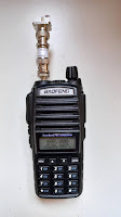
That's nothing new, it's cheap and worth trying. So I rigged up the multiplier shown in the picture with an unknown Schottky diode.

The Baofeng UV-82 RTX transmits between 400 and 521 MHz; that's plenty of choice to get an harmonic show up in the GHz range.

In order to check if it works I first looked for the harmonic on 10 GHz through an LNB, and sure it was where expected.

Unfortunately I did not see (receive) anything on 24 GHz, even at the higher power setting of the UV-82 source.


A better view of the diode and adapters.

Then I tried with a source that covers 2000 to 2990 MHz and there was no sign on 24 GHz while it was very strong on 10 GHz. I think the LNB amplification chain makes a lot of difference.

Still a 24 GHz module can receive another module at 12 metres distance with S9 and probably more once the antennas are properly aligned. I postpone the frequency measurement and spend time on checking which distance is possible in a radar-to-radar setup.


19 December 2021

Observations on CDM-324 (IPM-165)

After adding the sponge under the lid of two CDM-324 radar modules (probably clones on InnoSent IPM-165) I repeated the transmission-reception test over a range of 4 and 10 metres.

While the SNR does not deteriorate of a visible amount with the increased distance, I noticed few things about these radar modules.

They are very sensitive to power supply voltage variations. Any noise on the power supply line is reflected on the output frequency. I opted to use a 78L05 linear regulator and a battery power source.

The IF output(/input) has low impedance. I tried modulating via a 1+1 Mohm divider but no signal was available at the IF pin of the radar module and no modulation could be detected on the receiving end. I will try to lower the impedance of my source, or will move to Vcc modulation.

Sensitivity to surrounding objects is less than 50 cm. When moving closer than 50 cm to the CDM-324 there is noticeable frequency drift. When the obstacle is removed the frequency returns more-or-less where it was before. This effect could be used to generate a physical FSK modulation for slow visual CW, for example.

They are sensitive to temperature. This is not a surprise, as HB100 on 10 GHz feels temperature variations too. That's intrinsic to DROs. But on 24 GHz the effect is 2.4 times higher. As long as receiving and transmitting end are subject to the same delta_T, their frequency difference remains constant.

Given all the causes of interference to frequency output are minimised, the CW radar-to-radar reception looks like this:


The waterfall took about 60 seconds to build. Both modules where in the same small room in free-air, not enclosed in a box to add temperature hysteresis.

I think the current SNR should allow the reception over a 300 metres distance, which I will try once I manage to modulate them. That will tell some more information about the antenna pattern.


15 December 2021

Trying again on 24 GHz

Two years ago I briefly tried to use 24 GHz radar modules (CDM-324) for HAM operations. Back then I considered them not suitable, also considering that I discovered they lacked the RF sponge inside the lid.

Last week at a flea market I could buy the RF sponge, so it is worth trying again.

Now there is a sponge in the lid.

I built two circuits with a 78L05 and proper DC filtering. I could get two modules at about 70 MHz apart and the frequency is quite stable (in a constant temperature room). The good news is that the hand-effect is negligible and there is no modulation.

Next step is to add modulation.

BTW, I have lots of sponge in small rectangles in case someone needs it.

BTW2, would the sponge have some effect on HB100 too?!


10 December 2021

tinySA Windows software

A friend had a problem with tinySA Windows software, the one you can download here http://athome.kaashoek.com/tinySA/Windows/ . Everything looked fine, the COM port was recognised, just the software would not load. He got an error that a resource was not reachable, usable, accessible.

When I visited him I noticed that the Panda Antivirus from Panda Dome suite kept deleting the .exe every time I ran it. Even if the tinySA program was run as Administrator. While I am against whitelisting programs in antivirus software, it was the only way to get it running.

So if you are stuck in a similar situation with that software, find the way to convince your antivirus that it is bening.

03 December 2021

Reverse engineering a PCB - visually

In order to increase my "stock" of MG-17G 7-segment gas-filled displays, I bought a clone of the K80W calculator. It looks like many of them were produced and rebranded. The one I got had two (glass) broken tubes and something wrong in the electronics as only the rightmost digit would lit. Last but not least the faux leather case smelled nasty, so this calculator was set for dismantling.

Both PCB sides at once.
 

While I am against tearing apart calculators like these, this one was beyond repair and I already have a K80W needing a couple of new tubes.

As a sign of respect to the designers of this circuit I have decided to reverse-engineer it. In order to limit the handling of the stinky board, I opted for a visual method.

I shot a picture of the front and the back of the board paying extreme care to keep the (smartphone) camera at the same distance. Then using a photo editor program (The GIMP) I flipped the back picture, melted them together making one slightly transparent and the result is shown above. It's like a color X-ray scan.

Now I can work my way through the PCB traces either on the screen or on a printout.

Obviously this method works best with single sided circuits.