30 November 2023

Troubleshooting an Hameg HM203-6 oscilloscope - high voltage on CRT

I used the Hameg HM203-6 scope to test the Tennis-for-Two emulator I quickly built in November 2023. I also carried it to the exhibition venue as a backup. When it returned home I felt the urge to play with this analog oscilloscope that was lucky enough to be extracted from my pile of "probably to-be-fixed stuff".

So, what was wrong with it?

  1. compressed traces, about 0.7x shorter on both axes, and too bright;
  2. unblanking not working properly (it's the circuit that blanks the CRT electron beam when it returns to the left);
  3. rusty contacts.


Too high HV symptoms on a Hameg HM203-6 oscilloscope. For better viewing traces have been right-aligned. This way the unblanking problem is also visible.
Too high HV symptoms on a Hameg HM203-6 oscilloscope.
 

Hameg's were built when SMD was not a thing yet (mine is from 1988) and they use common (...back then...) parts. Therefore tracing the fault doesn't require a microscope and a replacement component can be found.

For the compressed bright traces I posted a request on eevblog and few fellas responded with very useful tips. Actually they noticed the problem with unblanking! The verdict is: High-Voltage is too high. It makes sense: higher voltage means faster electron beam that both gets less time for full deflection and hits harder the phosphor. I had checked the 150V line for deflection circuitry, which was fine. Sure enough the -1900V was at -2550V.

[Measuring kiloVolts is an interesting journey in itself and there will be a dedicated post.]

On eevblog was suggested that IC502, a 741 op-amp, might be faulty: "check that the voltage between inputs is few milliVolts max." I measured 455 mV, replaced the IC, -1900V was restored and traces "uncompressed". Considering the cost of a 741 I will not look any further for faults in the HV regulator, leaving a deeper inspection in case the problem arises again.

There is still the issue with unblanking. Something might have been damaged running at -2500V. There are three suspects: 68pF 2kV capacitors, the optocoupler, a couple of transistors. The latter two components are socket, most likely because they were prone to failure.

As for rusty contacts, they probably need some exercise, the most annoying being the "INV" button on both channels.

29 November 2023

Tennis for Two emulator

The secret project that went live on November 17th, 2023, was an emulator of the Tennis-for-Two game from 1958. It has been built for MuPIn - Museo Piemontese dell'Informatica - that held an exhibition of tennis (retro)videogames for the ATP Finals 2023.

Several videogames were on display and could be played, like the original Pong from 1972 up to a Wii.

There was a panel describing what should be the first videogame in history, the Tennis-for-Two developed to let visitors (taxpayers) of a USA laboratory interact with their technology. When I saw it I searched online for a modern emulator, found a 2008 project and I knew I could build it with parts I had at home. 

So who visited the exhibition in the second weekend could play an emulator or Tennis-for-Two on a Tektronix oscilloscope.

Fun fact: people spent most of their visit-play time at Tennis-for-Two and Pong games.

The video above shows one of my tests on my Hameg analog oscilloscope, shot with the smartphone that didn't want to focus on the CRT trace. Please refer to the link above for the circuit diagram and firmware (ATmega168 and up).


19 November 2023

PCB design: unfortunate position for a microcontroller IC

The last PCB I designed includes an ATtiny85 microcontroller. Since it will not need many updates I did not include the ICSP header for reprogramming. The first time I needed to swap out the '85 I realised I forgot to leave some room for pulling the IC from the socket. HAH!


I usually insert a small flat screwdriver under the IC and gently lift it up. In the configuration above it is impossible to get in from the left and just slightly easier from the right paying attention to the resistors.

Lesson learned.


17 November 2023

Teaser 2 - secret project

Second part - of three - of the secret project going live in 4 hours in Torino...


Teaser - secret project

This board is from a secret project that will go live tonight at an exhibition. I realised I could build it last Sunday and I knew I already had everything at home, like a good lot of 4k7 resistors :)


This quick project obviously got highest priority and everything else went into stand-by, like the optical TX/RX and 24 GHz.

Looks like November is the month of self-imposed challenges for me.


01 November 2023

OptoSupply OS5RKA5102P and OS5RKA5111P THT ultrabright LEDs

Lately I am playing with LEDs, trying to build a pair of optical transceivers. The TX side will use some very bright 5 mm red LEDs made by OptoSupply. I chose those with 8° and 15° beamwidth. They are OS5RKA5102P and OS5RKA5111P respectively and they should emit 100'000 mcd each, which is quite impressive, also on your retina if you look straight into them.

For the records, one TX will have 8° LEDs, the second will use 15°.

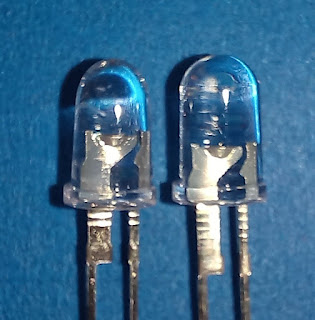
Besides their weird leg shape that requires a custom footprint (I've done it for KiCad) the problem with these LEDs is that they look very similar and you can easily mix them. So, here is a closeup that helps distinguish which is which.

Close-up picture of narrow beamwidth OptoSupply LEDs.
Left is the 8° OS5RKA5102P, right is the 15° OS5RKA5111P.

Left is the 8° OS5RKA5102P, right is the 15° OS5RKA5111P. Physically the 8° has a narrower body, larger anode area and smaller tab on the anode leg.


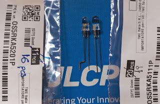
LEDs and the bags they came in, to confirm part No.!

While testing the 4x4 array I noticed that one LED was dimmer: a closer inspection confirmed that I had soldered a 15° LED amongst 8°. If they worked with the same current that wouldn't be a bit problem, but it is not the case with these two models.