25 March 2020

Canon Palmtronic 8M

Palmtronic LD-8M 3
After the Litronix 2235, I found a "Canon PALMTRONIC LD-8M 3". That is what tells the battery cover in the back. This calculator was being sold without batteries and with the faux-leather soft case.

After the routine cleaning and some action on the power button, it comfortably showed "0" in the rightmost position.

This is a basic calculator with square root, percent and memory.

Buttons feel OK and don't bounce causing typing errors.

Calculator and soft case.
Battery cover with "LD-8M 3".

Now I own two working Canon Palmtronics, the first being a LD-84. Both came without battery damage. A curious coincidence.

Negative number.

24 March 2020

Let it loop

Being in COVID-19 lockdown gives me the opportunity to be on the air during the day, once work time is over. I tried a magmount 20m Diamond mobile antenna on the East-facing balcony, but I managed one contact with my sloppy CW. Well, RBN receivers had me around Europe. But no contacts were possible in PSK31, neither a report on pskreporter service!

So I moved to something different: a magnetic loop. It had to be build with readily available materials: a hula-loop diameter 70 cm (then not needed to keep it in shape), 4 mm solid coax cable (it's too thin for a permanent loop!), a dual-gang air variable capacitor (two sections in series giving 10-130 pF) and FT817 to tune the antenna sur place.

The feeding loop is just a piece of coax "1/5th of the main loop" long. From the coaxial line, the center goes to braid of the small loop on one side, and the coax braid to the braid on the other side. In other words the feedline is terminated with a 44 cm long loop made of thick wire.

It took me a couple of hours to build. Most of the time was spent looking and implementing a solid mechanical solution for the variable capacitor.

The picture shows the resulting loop. It tunes 30 to 10m. On 20m it is about 20 kHz wide for 2 SWR bars on the FT817.


11 March 2020

Litronix 2235

Litronix 2235.
I had the opportunity to visit Torino's flea market "Barattolo", that is (currently) held every Saturday and Sunday. This is where you can find the cheapest used garbage things. It is not as large as Hrelic in Zagreb, but it shares the same philosophy.

I did not have much time and it was almost time to pack up for everyone. Nevertheless I could find three 1970's pocket calculators, which required a bit of successful price negotiation.

How I got it.
First in the blog show is Litronix 2235 with very curious LED display from 1975.

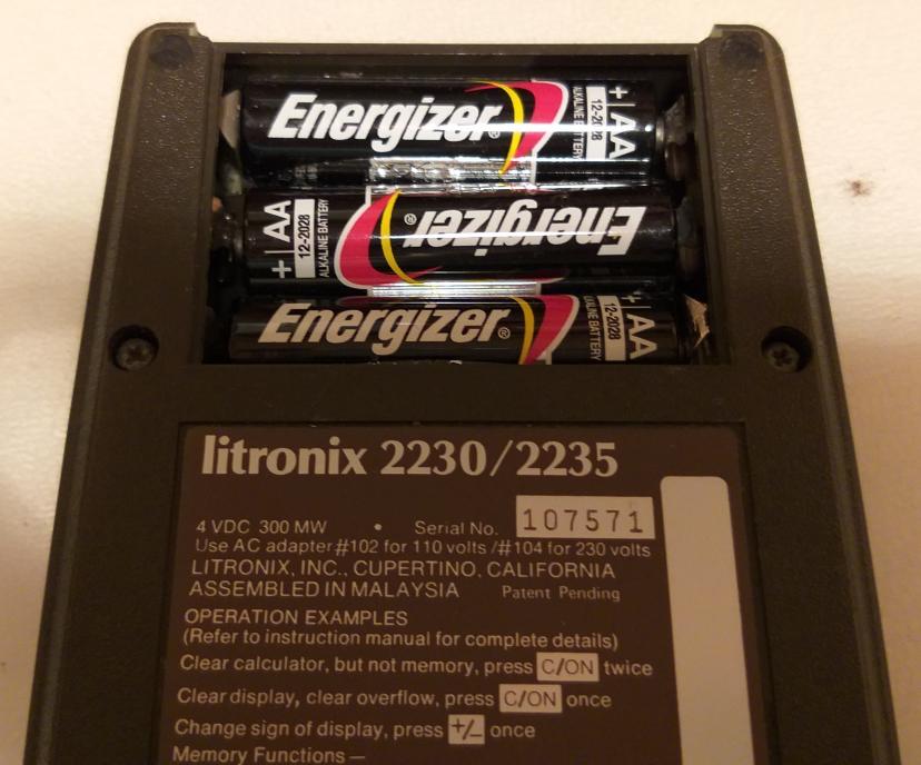
It felt heavy, a sign that batteries were inside but it did not switch on. Good cosmetic conditions, though. When I removed the battery compartment lid, I saw a little horror show (see picture). One AA battery had even cracked! Nevermind, that is the kind of trouble that I am looking for.


Fresh batteries!
Fortunately the leak had not spread to the circuit, probably because both of the position of batteries within the case and how it was stored. The worst block of salt was on a removable part, that had a bath into pure white (apple) vinegar and a was under tap water. All within 10 minutes time. The plating is now gone, but contact is restored.

Three AA batteries later the Litronix 2235 LED display said hello. It is an 8 digit calculator, but it has a 9-digit display. That's because a decimal point is shown in the position of a digit instead of being subscript intra-digit. What makes it even more peculiar is a dim LED showing that there is Memory content in the upper-left corner of the display.

The LED display. Can you see the small dot in upper-left corner?

27 February 2020

DOS saves - A tale of retrocomputing

It is early 2020 AD and I am developing some Arduino firmware for a friend. I chose Arduino for several reasons, one of them is that the friend in his 70's can program Arduino clones using a legacy PC that runs Windows XP. You know, HAM and electronics enthusiasts have a bunch of equipment that requires software/drivers that have never been updated/ported to newer operating systems: so why change it, when it works?!

My computer runs a supported Ubuntu distribution and the latest Arduino IDE. Actually our Arduino IDEs are not too far apart version-wise, so I started sending him updated .ino source code.

First problems appeared with I2C LCD driver libraries that misbehaved: there are too many with the same name and you can't know which one is being used at compile time. This forced me to find an I2C LCD library with a different name than LiquidCrystal_I2C, which is actually better than others:

#include <hd44780&.h> // main hd44780 header
#include <hd44780ioclass/hd44780_i2cexp.h> // i2c expander i/o class header

This solved it, but the same firmware worked differently on his hardware than mine. What broke was a function that picks a random value and looks it up in a static table, which went out of bounds. This happened at the second iteration of the main loop() and then the firmware basically crashed.

Since it didn't happen on my side, one solution was to send him the compiled firmware (.hex) and burn that directly. It is fairly easy: have Arduino IDE print out the avrdude programmer command and replay it with the .hex that you want to load. I planned to do it over TeamViewer, as I had done few years ago.

Second problem: his WinXP has TeamViewer 10 and cannot be upgraded, while on my Ubuntu I got TeamViewer 15. They don't talk to each other. Fair enough. TeamViewer guys let you download old versions (excellent!), so I installed 10 on my Ubuntu, but it still refused to connect. No time to troubleshoot that, so I switched to Plan B which required a bit of preparation: blindly write down the instructions and have my friend do it without my real-time assistance.

Once I got from him the complete avrdude command (in form of screenshots because you cannot copy the debug output in Arduino IDE!), I needed the safest way to get him on the right track. Consider that I do not have a Windows machine to try the procedure beforehand.

So, I produced a DOS batch file hoping that the Arduino board would end up always on the same COM port. The simplest thing was to put everything in C:\ so to avoid long paths. A .bat file cannot be sent over email, so it was a .txt then renamed. Once I explained to click on the batch file, nothing happened: the DOS window just flicked quickly. I needed to see the error message.

We worked out together an old DOS trick: pause the execution of the batch. He remembered the right command was "pause", so he did everything on his own to edit the file, rename and run again. I could now see (a screenshot) that I had misread an avrdude flag in "1" rather than "i". So, one more edit and run and .... mission accomplished! DOS saved us.

Even better, he managed to program a second Nano board that ends up on COM10 simply editing the batch file.

My binary firmware works as expected on his hardware, no more array out-of-bound and firmware crashes. His Arduino installation probably has stale libraries or doesn't work properly on the experimental now-dead WinXP 64 bit.

For the next updates I will send him the .hex microcode and all will be fine. And if something else goes wrong, there is always DOS!


11 February 2020

TIL311 clock and fun KiCad project

PCB travel box :)
While in the past I tried (and not documented) to wire four TIL311 displays on perfboard, I quickly realized the project would need too much wiring to be fun and relaxing. Fast forward a couple of years and a positive experience of PCB design with KiCad, I decided to refresh the whole process.
 

PCB under vacuum
This time I would design a PCB composed of two detachable parts: one with the logic and another with the display. This way I can choose between two physical layouts and reuse the logic board for other projects, provided a new display or daughter board is designed.


Few requirements for the logic board in order to exploit TIL311 peculiarities:
  • per-digit independent dimming control (needs PWM outputs),
  • per-digit latch control (obviously),
  • common BCD DCBA bus to all displays,
  • independent LED voltage vs logic voltage (to reduce heat generation and thermal stress on TIL311),
  • free form management of embedded decimal points (provide pads on PCB, wire later).
 Further on, from my previous experience as clock builder:
  • interface to common I2C RTC board
  • interrupt driven time base,
  • build-time choice of 1 pps or 32 kHz interrupt from RTC
  • LDR for dimming
  • button + potentiometer to handle user interaction

Click and zoom for details.
This time I ordered 10x PCBs from JLCPCB.com . I chose black finish because I think it matches best the red-purplish displays. I did a DIY panelisation in the sense that I drew a line where it should be cut, and I do it with a cutter if needed. They arrived in a sturdy cardboard box. Click and zoom in the picture to see how the small font has been printed.

And here it is, #1 clock resulting from this project. It turns out that the RTC module doubles as a standoff, so the whole thing stays upright in a nice-looking position for a desk.

A 4x TIL311 clock with Arduino Nano.

10 February 2020

Sostituzione pistoni a gas sul pensile della cucina

Nel 2008 ho comprato una cucina con due pensili in vetro/alluminio con apertura a vela, sostenuti con un meccanismo a pistoncini a gas: lo scolapiatti (90 x 70 cm) e sopra i fornelli (90 x 62 cm). Nel giro di tre anni i pistoni si sono scaricati ed ho provveduto alla sostituzione. Passano altri tre anni e di nuovo, i pensili non stanno su. Altra sostituzione, questa volta con pistoncini Effegi Brevetti Stabilus Lift-o-Mat 6011SE da 450N contro i 350N originali (stesso produttore). Questi durano 4 anni sullo scolapiatti, ma alla fine cedono.

Siamo nel 2020. Già da tempo ho maturato l'idea di sostituire le molle a gas con qualcosa più moderno, dato che le stesse case produttrici non li usano più dal 2008-2009! Faccio un breve giro in mobilificio per curiosare cosa montano, salvo scoprire che non sembrano più fare pensili così grossi con anta unica.

Non importa, insisto e scopro il catalogo della Blum. Hanno meccanismi per aperture di tutti i tipi e tutti i pesi, incluse le mie vele da 8.5 kg! Studio il catalogo, capisco i pezzi che servono ed arrivo a queste cifre:
  • due coppie di pistoncini Stabilus Lift-O-Mat, 50€/coppia, totale 100€
  • meccanismo completo Blum (molla, bracci, ancoraggio anta), totale 204€
Il meccanismo Blum Aventos HS consente inoltre di fermare l'anta a mezz'aria (una volta regolato), cosa non possibile con il meccanismo originale.

Non avendo intenzione di cambiare cucina a breve, ho scelto di spendere il doppio e liberarmi del patema di ottimizzare le aperture delle vele per ridurre i cicli. E divertirmi con un po' di sano bricolage da raccontare agli amici. Senza contare che i pistoni a gas sono sempre più merce rara.

Ho fatto il lavoro in autonomia e senza smontare il pensile dal muro. L'anta ovviamente deve essere rimossa (in due persone!), va fatto qualche foro con attenzione, ma soprattutto ci si può liberare dei pistoncini a gas!!

Le foto mostrano l'interno del pensile prima e dopo l'intervento. Ci tengo a precisare che sono semplicemente un cliente soddisfatto e non ho avuto contatti con la casa austriaca. I pezzi Blum li ho comprati online, in Sicilia. Lascio a voi individuare la casa produttrice della cucina.

Prima, il "peccato originale" della casa.

Dopo, meccanismo Blum.


Cortesemente lasciate un commento se questo post vi è tornato utile, perché in rete non ho trovato praticamente nessun riferimento ad interventi come questo: ho avuto solo io il problema, o nessuno ha condiviso?

21 January 2020

Arduino Nano has no INPUT_PULLUP on A6 and A7

I discovered it the hard way: Arduino Nano has no INPUT_PULLUP on A6 and A7. That's because the ATmega328 in tiny SMD package has two extra pins (vs. the DIP processor), which are tied directly to the A/D converter MUX without the digital I/O logic.

I discovered it once I received and assembled PCBs for a TIL311-based clock, where I used most - if not all - I/O and analog functions were left to "pure analog input" pins A6 and A7.

Well, wiring an LDR between A6 and ground lead no readings. Few measurements later, and a quick Internet search, revealed this hard truth.

Fortunately I have an easily accessible 5V point near A6, so I could throw an external pull-up resistor.

14 January 2020

Voltage multiplier

It is all right at IK1ZYW's Labs, it's just that I had no opportunity to update the blog.

Last experiment has been a voltage multiplier as Cockcroft-Walton designed it in mid 1930's. Why? Apart my quest for a HV PSU (in the order of 300 Vdc), Xmas lights came with powerful 24 Vac 20VA transformers that should be enough to power some Nixies, once voltage-multiplied.

Electro-party!
The hardest part has been to locate high value capacitors with high voltage rating in and around the junk box. While 2-300V rating is not hard to come by, the high capacitance is required in order to keep low its AC resistance at 50 Hz. Diodes need to sustain at least 60V reverse polarity, so 1N4003 and above.


I started with 220 uF capacitor, but it got too warm. Then I replaced it with 2200uF 63V in the first stage and everything got better. With 4 diodes I reached more than 160 Vdc which happily light up an IN-14 Nixie without dropping more than a Volt.

Nice experiment so far. A final circuit would allow to pick different output voltages stepped at (24*1,41) Volts, which can be useful.

Or just put back-to-back two of these transformers, rectify the output and find a way to drop it to the desired value. Thinking ...