28 June 2016

Friedrichshafen 2016

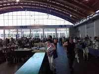
I couldn't miss a second visit to the largest ham fair in Europe, so there I went last Friday. My main interest was the flea market, and that's where I spent almost 8 hours. My feeling is that there were fewer people and less sellers than 2015 edition, but last year I spent two days and I might remember the Saturday crowd instead.
 
I was looking mainly for old display technologies, and it wasn't that bad.
 
I bought:
  • IV-27M VFD (5 EUR)
  • IV-22 VFD (2 EUR each)
  • a board with 4xZM1000 and 1xZM1001 from Philips PM2421 (10 EUR) ... this is as old as I am!
  • B5092 and alike sockets (50c each)
  • two nice shaped valves (1 EUR each)
What I haven't bought:
  • red-coated top-view DDR Nixies (used starting at 3 EUR, new up to 10 EUR)
  • the case around the Philips board
  • another Philips board with case (26 EUR)
  • a 20 GHz frequency counter with Nixies, working (280 EUR)
  • a DVM with 4-digit Nixie display (70 EUR, fair)
  • another frequency couner with Nixies the person at the table couldn't find out the price
  • a desk microphone from 50's, nice design (5 EUR)
  • a desk clock-radio with a flip clock (obviously missing one palette)
What I haven't found:
  • early days spare LED displays (late 70's)
Now it is time to test my purchases. IV-27M will go first, then find out about the nice shaped valves and power up the board with ZM tubes. 
 
View from a corner of A1, new stuff.


Almost a panoramic view of A4,
from the rear end of the hall.
 

07 June 2016

A clock with Arduino and four HP 5082-7300 displays - 3

Last part in this series about building a clock with four HP 5082-7300 displays controlled with an Arduino.
 
After using the HP 5082-7300 desk clock for a whole day and night I came up with few improvements.
 
First of all, during the day nobody will look at it; why keeping it running, then? The are many ways to control it via software, like switching off the display according to the time of the day, to the room brightness, to a physical presence and you can certainly come up with other ideas. Instead of developing a software solution I will add a switch to control DC power to the whole circuit.
 
Meanwhile I wrote and applied some firmware updates. The first refinement is meant to reduce heat production, which occurs during the day when nobody looks at the clock: cut in half the display brightness at the higher luminosity levels. It does have an effect since the top of the box is not warm anymore. Then, since every digit has the decimal point, the new firmware moves around the dot endlessly instead of just blinking the central one. Third and last change was to read the LDR value once a second instead of once every PWM loop: this makes the loop a bit faster (ca. 0.1 ms) thus reduces flicker.
 
A further improvement could be to add some hysteresis and averaging to the intensity control, not counting adding further digits.

The firmware is available on github. Homework: are there other functions I have not described in these three posts?

05 June 2016

A clock with Arduino and four HP 5082-7300 displays - 2

Part two of how I designed and built my own bedside clock with a 1970's touch.

The finished clock, in the operating position.
This time my adventure started from the enclosure: a wooden box with the top cover almost completely transparent I had bought to use with a VFD clock but turned out to be too tight for it. Inside there is enough room to fit the whole circuit and ensure air flow for heat transfer (remember an HP 5082-7300 dissipates 500 mW on average!).

I have read online that these displays fail mainly because of overheating or stress from prolonged heat. I do have few spares but I really care to do my homework properly!

Therefore I cut a piece of perfboard to the desired size and started planning the layout: displays would be on the upper-right corner and the rest underneath. I decided that everything should be visible through the glass window (except for wiring) so that it would be easier to describe the clock to friends visiting my place (in that case the box will be moved to a more visible spot, like the kitchen furniture). Nevertheless I tried to keep a clean wiring scheme, pleasant to be seen.

Since these displays have a Latch Enable line, they keep displaying the digit once it has been loaded into their internal buffer. In order to drive these displays I need:
  • 4 lines for the 8421 BCD code
  • 1 line for the decimal point
  • 1 line for each display (4)
Lid open.
So it is 9 lines going from the Arduino-like to displays. Instead of running them through the board I used a set of pin headers just in case one day I will decide to separate logic from display areas. This holds true for +V and GND as well. The effect is a bunch of colored wires connecting two areas of the single board: they add a touch of color :-)

The RTC board is a cheap battery-backed DS1302 I2C module that appears to be pretty stable. I added an LDR to do brightness control (ADC in microcontroller and PWM control on displays) and made provision for two pushbuttons that help setting the time.

As microcontroller board I chose a clone of Arduino Nano v3, because it is small and still has a strong USB socket for firmware updates.

Given the power requirement of HP 5082-7300 displays I need an external PSU, but since I want to run the whole thing at 4.2 V, I had to add a further switching step-down module inside (on the back of the perfboard).

Isn't display brightness affected with the lower supply voltage, you may ask? It is indeed, they look dimmer (and dissipate much less power!), but I will look at this clock at night in a dark room, so that's what I am looking for afterwards! The voltage can be even lower, but then brighness is not even anymore.

And after running it for 24h I came up with few firmware adjustments, covered in the next article of this series.

03 June 2016

A clock with Arduino and four HP 5082-7300 displays - 1

I needed a time display on my bedside table and I wanted it with an electronic vintage touch. So I gathered:
  • 4x HP 5082-7300 displays
  • an Arduino-like board
  • an RTC module
  • a perfboard
  • some female pin headers
  • wire, solder, tools, ...
  • a 5 Vdc source
Optionally:
  • an LDR
  • a couple of N.O. pushbuttons
Four HP 5082-7300 displays.
An HP 5082-7300 display is an early LED display developed before 7-segments became the de-facto standard. It includes a BCD decoder and it displays 0-9, dash and blank and a right hand side decimal point. Each segment is composed of few LED dots, so it mimicks a dot-matrix display. It works from about 4 V to 5.5 V and it drains an average of 100 mA at 5 V: that's half a Watt per display! We are talking about late 1970's technology.

So, why using these power hungry displays in 2016? Simple: to learn something new and to save old technology from the recycle bin. Moreover a modern microcontroller makes it very easy to produce a BCD sequence that represents the time of the day.